As we all know AMD motherboards need BIOS updates to support new generations of Ryzen CPUs. This can normally be done by using a recognized older gen CPU to power on the board and access the built-in BIOS updater function. This, unfortunately, requires the older gen CPU to be around and available for the procedure.
Hardware
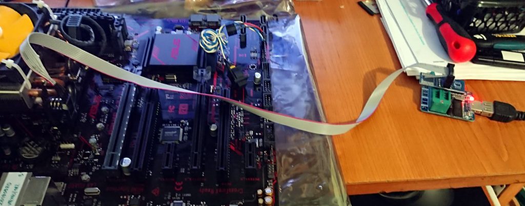
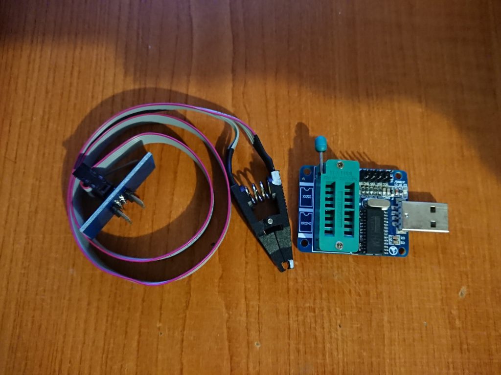
When there’s no older gen CPU around to use or you’re simply in the mood for some hardware tinkering, you can get your elbows dirty (figuratively, since the board is brand new and not dusty yet) using an EEPROM programmer (eBay / AliExpress). The in-circuit programming clamp accessory will be also required to connect to the BIOS chip without de-soldering it from the board.
I’m using a cheap CH431 based USB programmer which supports plenty of the 24 and 25-series EEPROMs:
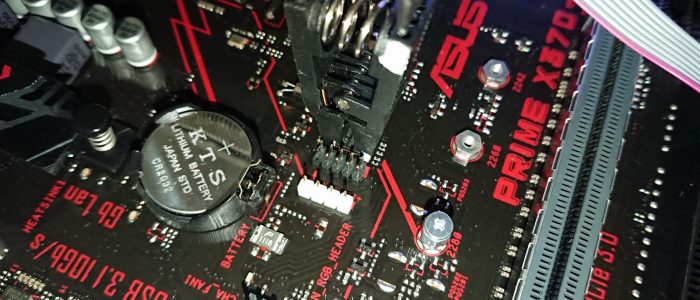
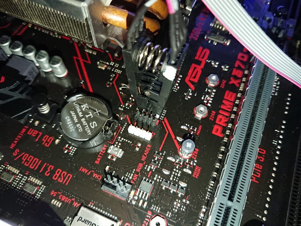
First step is to identify the BIOS chip on the board – on current generation boards it’s usually a small 8-pin SOIC-8 chip located somewhere around the CMOS battery. When you think you found it, read its identification number and look it up to confirm.
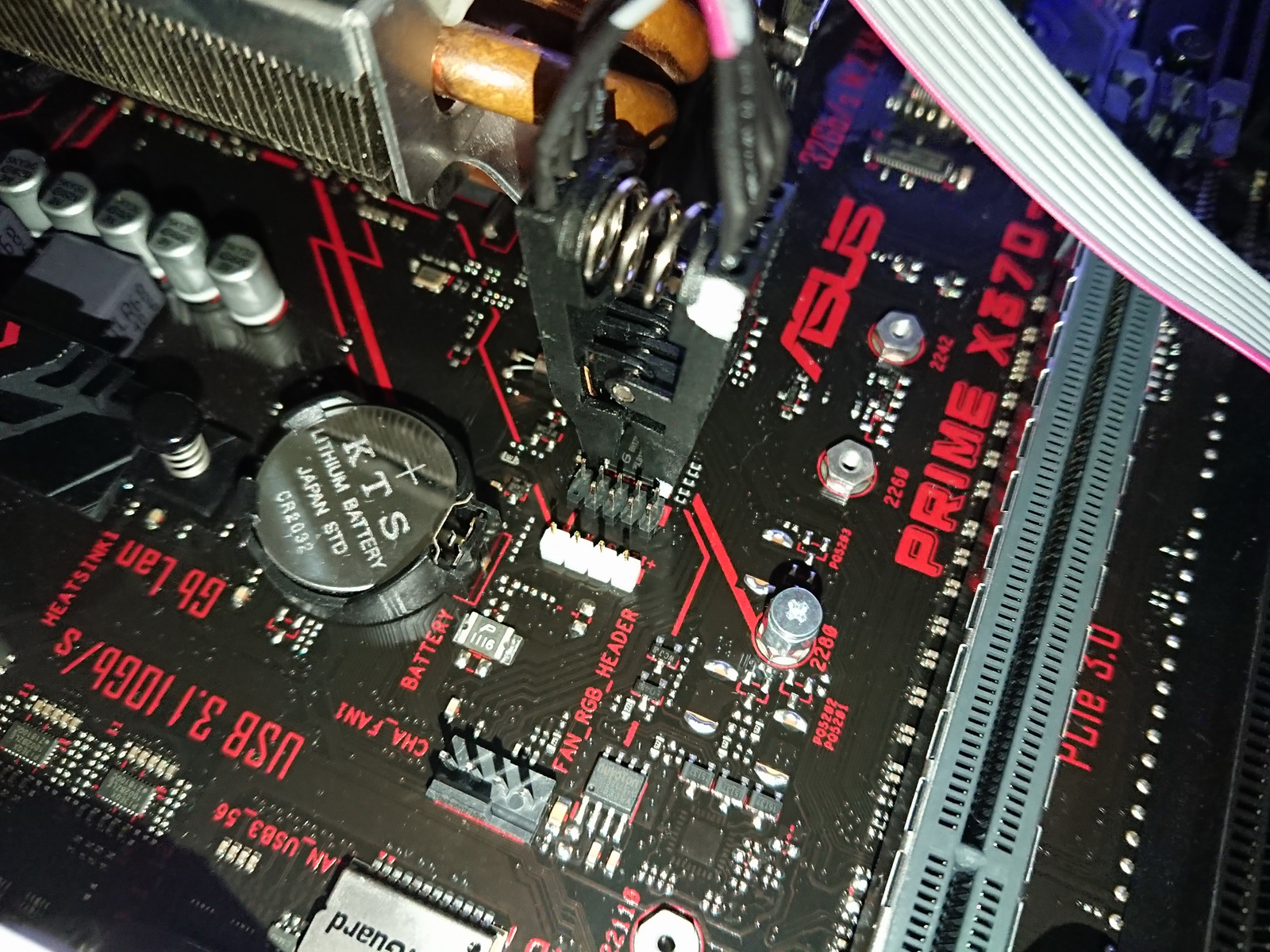
My board uses a 25LB128, which is a 128-Mbit (16MBytes) serial flash. Identify pin 1 (it’s normally indicated by a dimple or a dot on the chip package) and attach the programmer clamp to it with the correct pin orientation.
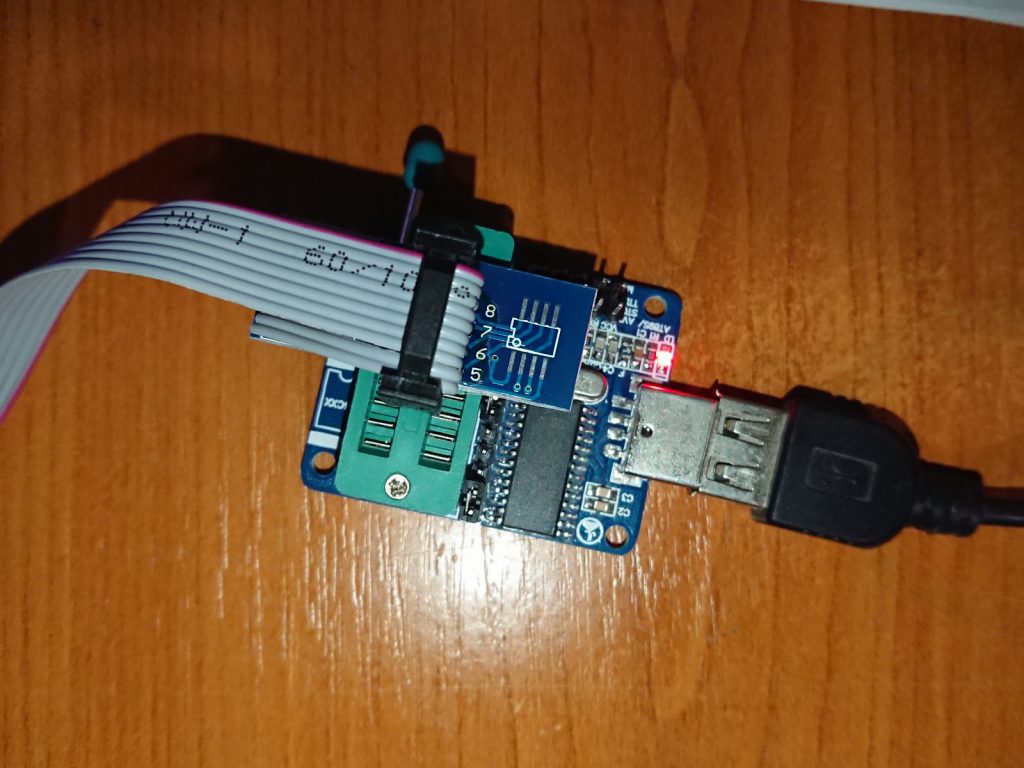
After making the connections (always double check that the pin alignment and numbering match on the programmer, the extension and the chip), plug the programmer in the computer and start up its software. Use the programmer’s Identify chip procedure or manually select it from the supported list then attempt to read the chip’s contents.
 Software
Save the extracted content to a file. If you’re having any trouble with the read process make sure that the connections are firm (cheap tools aren’t the most relying ones). Verify the read process to ensure no data corruption occurred.
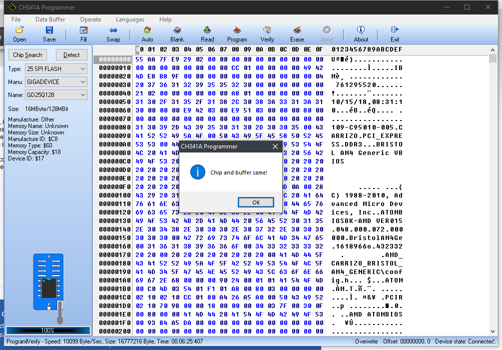 Download the most recent BIOS update file for your motherboard and extract it – you should obtain a .bin / .cap file. Unfortunately, you cannot use this file directly to program the BIOS as it contains extra identification/verification code. You can confirm this by comparing the saved BIOS and the downloaded file with a hex comparator.
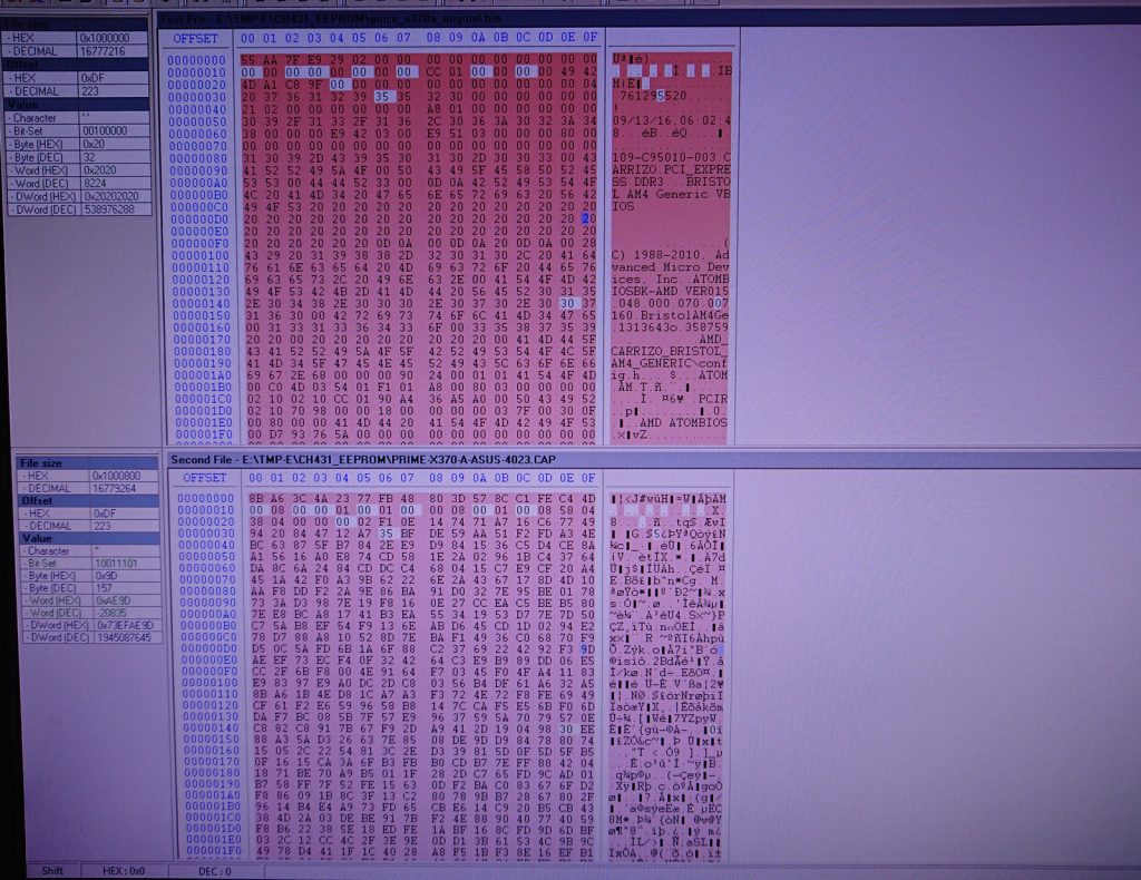 As you can see in the image above the .cap file has additional content in the header of the file (the saved BIOS begins with the board identification strings directly).
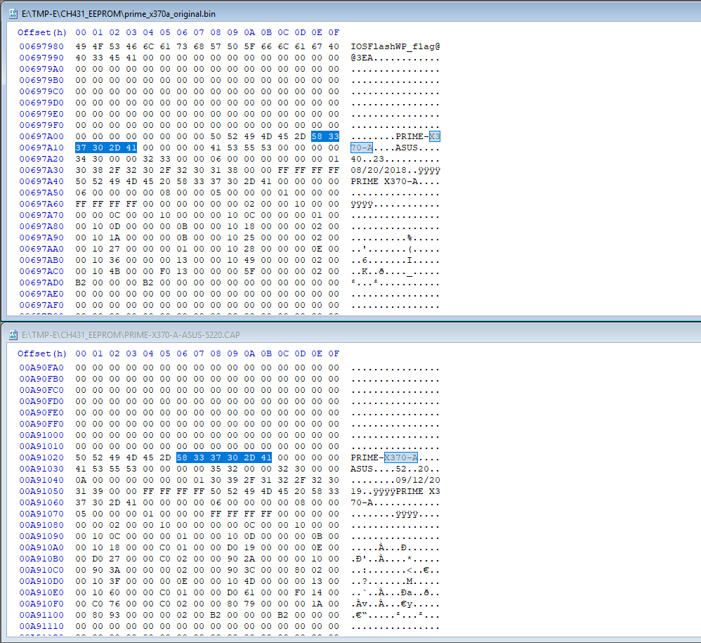
If you care to find out what BIOS version the board is currently running, you can search for its identification name in the saved file (the version number is usually close by). As can be seen in the image below, the board was running version BIOS version 4023 (from August 2018), while the update is 5220 (from September 2019).
 To obtain a writeable BIOS image from the downloaded .cap file, you’ll need to use UEFITool to extract the correct content.
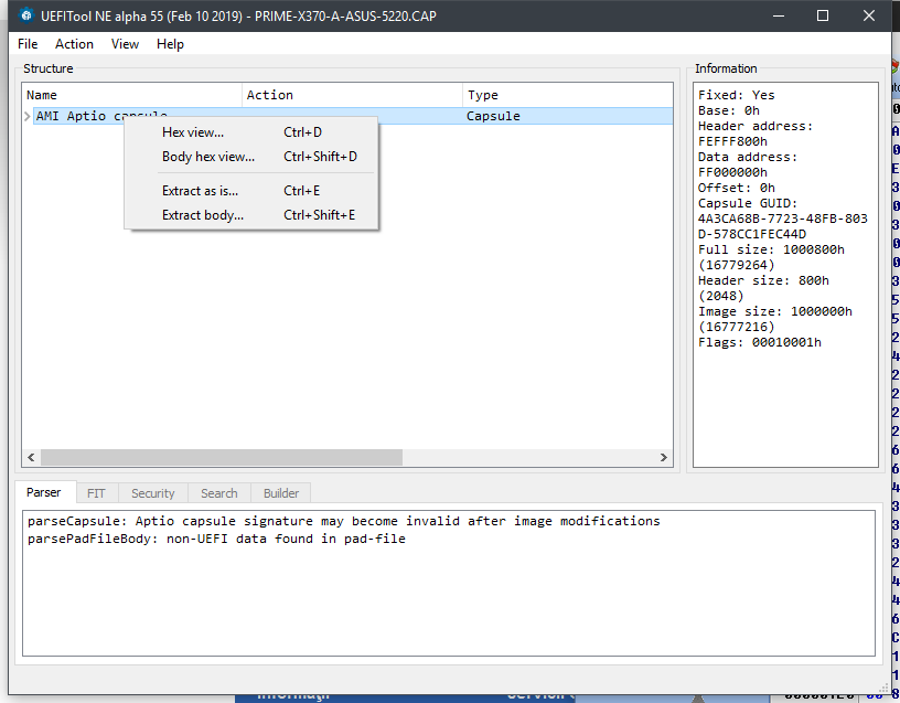
Open up the .cap file with UEFITool and right-click on the “AMI Aptio capsule“. Then select “Extract body…” from the menu to obtain the writeable bios binary file.
 Compare the newly saved file with the original BIOS read from the chip to ensure they have the same structure (also check the files’ sizes, they should match right down to the last bit)
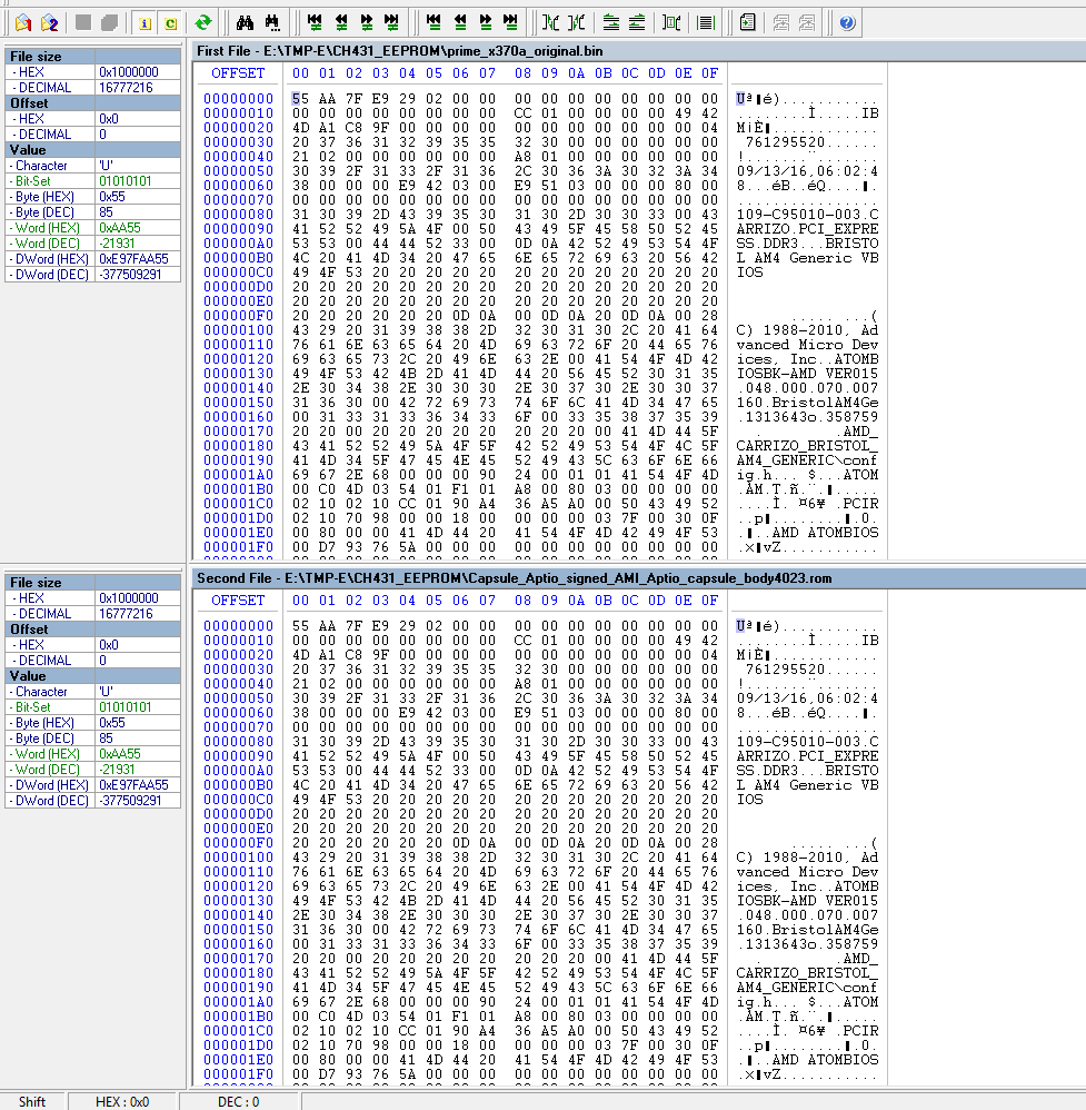 Here I compared the BIOS image read from the board with the BIOS image extracted with UEFITool of the same (old) version to check for any differences that would indicate the procedure would fail. In my case, the two images were identical so whatever UEFITool extracts from the .cap file should be writeable to the chip directly. Comparing the old image to the newer extracted version would obviously show differences.
After extracting the latest BIOS image with UEFITool, if the structure (heading and footer) look similar and the files sizes match perfectly it should be safe to program the BIOS with the new file.
Return to the programming software and load the extracted binary file. The EEPROM needs to be erased before write, so use the Erase function. Check that the chip is blank with Blank.
With the chip blank and the extracted BIOS image loaded, click Program and wait for it to write the data then use the Verify functionality to check that the write was successful.
 Once that’s done you can disconnect the programmer clamp from the BIOS chip and connect the motherboard to the rest of the computer and attempt boot up.
Success
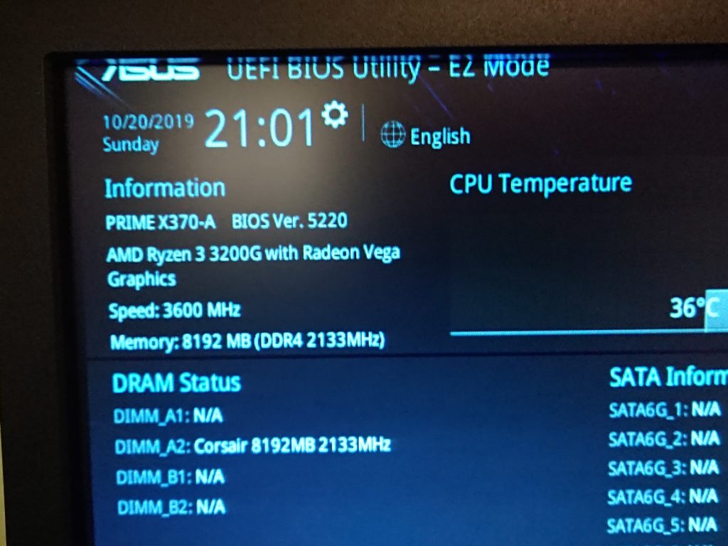 In my case the procedure worked from first try (although I had to erase and program the chip several times, most likely because of imperfect contacts between the chip and the clamp).
Your results may vary (and the file structure and extraction procedure may differ with other motherboard vendors and also with time).
Software used:
- CH341A Software and drivers – (
local copywas detected as harmful by Google even though deemed clean by any other sane scanner)- CH341A driver from chip manufacturer
- alternative CH341 programming software – I’ve had reliability issues with read/write operations
- second alternative CH341 programming software
- UEFI Tool NE alpha 55 win32 – local copy
- Fairdell HexCmp2 (shareware)
Is your flasher supports 1.8v chips by default or did u make any adjustment to it?
This question never crossed my mind, but since the 25LB128 I worked with is a 1.8V serial flash chip and it didn’t burn it, I guess it does.
Which version of the program did you use? Thanks
I have both versions 1.17 and 1.18 of the program shown in the tutorial.
I won’t link to them because Google is crap, but if you already have a copy that doesn’t work you could try this alternative programmer.