The hardware
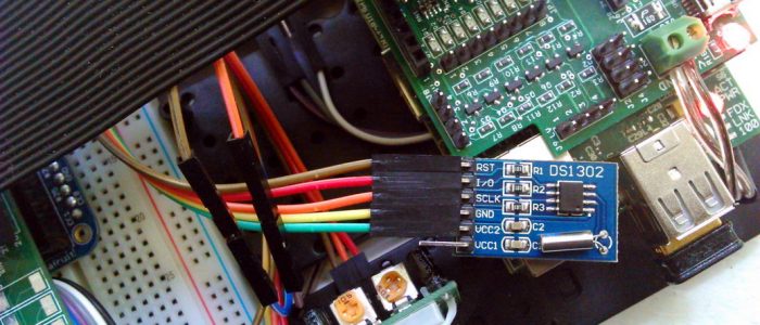
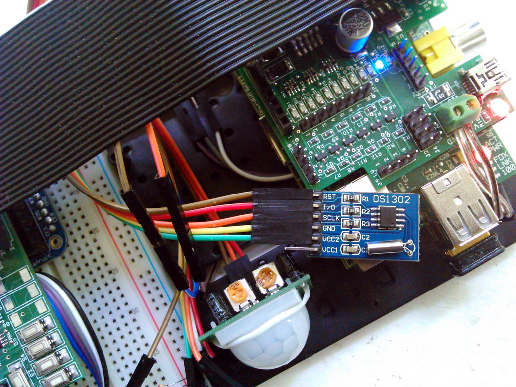 I’ve got a “DS1302 Serial Real Time Clock with Battery” very cheap off eBay (for under 2$) which I’ve set up as a backup Real Time clock module on my Raspberry.
Hooking it up is pretty straightforward. You’ll need power (3V), ground and 3 GPIO pins (which are hard-coded in the C++ program and rather difficult to change).
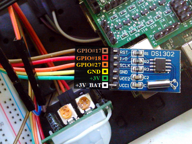
The pinout is detailed below:
| Raspberry Pi | DS1302 Module |
|---|---|
| not connected | VCC1 / VBAT *this pin is connected to the module’s battery and should not be used |
| 3V (pins 1 or 17) | VCC2 |
| GND (pins 6, 9, 14, 20 or 25) | GND |
| GPIO #27 (pin 13) *GPIO #21 (same pin) on PI rev1 |
CLK |
| GPIO #18 (pin 12) | DAT |
| GPIO #17 (pin 11) | RST |
The software
Download the source code and compile it with
cc rtc-pi.c -o rtc-pi
Edit: This code and tutorial were written at a time when only one edition of Raspberry Pi (the 1) was out there. For the newer Pi-es which added extra GPIO pins and rearranged some of the existing ones, the code may required adjusting to address the correct pins, as mentioned in the comments below.
Then you can run
sudo rtc-pi YYYYMMDDhhmmss
to set the time and
sudo rtc-pi
to read the time from the module and set it to system clock
Syncing PI clock with module
A RTC module would be useless on the PI without using it to retrieve the right clock at the right time. And the PI needs a clock the most at boot.
The simplest method would be to edit /etc/rc.local and add a call to the compiled rtc-pi binary.
But to read a valid clock from the module we require it to have the correct time set beforehand. For this we can use the same binary to save the correct time (obtained most likely via NTP) on a previous shutdown.
For this, create a new file (let’s call it savetime) in /etc/init.d with the following content:
#!/bin/bash
# saving date/time to RTC module
/usr/sbin/rtc-pi `date +"%Y%m%d%H%M%S"`
Then symlink this file in /etc/rc0.d
ln -s /etc/init.d/savetime /etc/rc0.d/K01savetime
rc0.d is the folder for scripts called at runlevel 0 (shutdown/restart)
Additional information: (1)
Are the settings deffer according to the OS on the SD card?
Hi,
Thanks for the tutorial. I connected the RTC , copied the c file to RPi and ran the code sudo rtc-pi YYYYMMDDhhmmss. It seemed to work well. But when i tried sudo rtc-pi , it gave error
Read UNIX timestamp from RTC: -1
Unable to change the system time. Did you run the program as an administrator?
The operation returned the error message “Invalid argument”
Can you help me with this?
Depending on the RPi board being use you could need to change the address for the GPIO in the rtc-pi.c file. I was using a RPi 4 and didn’t got a response from the DS1302 with the original code. i changed #define GPIO_ADD 0x20200000L to #define GPIO_ADD 0x3F200000L and got the same error. Then i changed the line to #define GPIO_ADD 0xFE200000L and it worked just fine.
On Raspberry Pi 3 I changed GPIO_ADD to 0x3F000000 and it works now
@Claus 0xFE200000L works on my Pi 490 as well. I guess it’s the same SoC.
Hi
sorry for my english
how can i change the GPIOs?
thanks
I coyped the rtc-pi .c to my RPi sd card but when I type cc rtc-pi.c -o rtc-pi in my RPi model A+ is tells me there is no file or directory
Could you use this to hybernate your pi and wake it up?
Thanks for the pointer to e-bay for inexpensive TOY clocks.
I reviewed the software and it appears to create a bus conflict when reading the TOY registers. It also
has other issues.
I have written a replacement, but until my hardware arrives, it is simulated but untested.
Meantime, beware.
What is the value for rpi zero w?