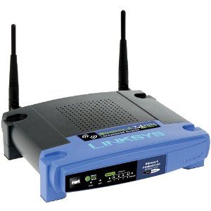
I got a Linksys WRT54GL v1.1 router that somewhat worked and somewhat didn’t: it booted alright (no led errors), responded to ping on its default IP (192.168.1.1), bot other than that, it did not respond on the web interface, nor telnet/ssh, nor dhcp.
I tried the 30/30/30 reset , tried TFTP recovery – nothing worked.
As it had the original Linksys firmware, at this point it was either a hardware failure or the only recovery course would be the JTAG reflash.
The JTAG connector
This was the trickiest part for me, mostly because I found plenty contradicting information on the internet.
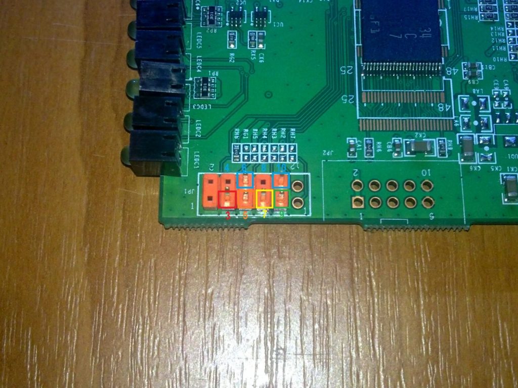
The router has two unused connectors on the board, named JP1 and JP2. JP1 is a 12pin connector, while JP2 has 10 pins. Some tutorials (mostly those written for WRT54G routers) used a 10 pin connector for the JTAG cable, others used the 12pin one. But Linksys routers should all have the same layout, right? – wrong! On the WRT54GL v1.1 the JP1 12pin connector is the JTAG one, while the JP2 10pin can be used for the serial ports (if you want to do that mod too).
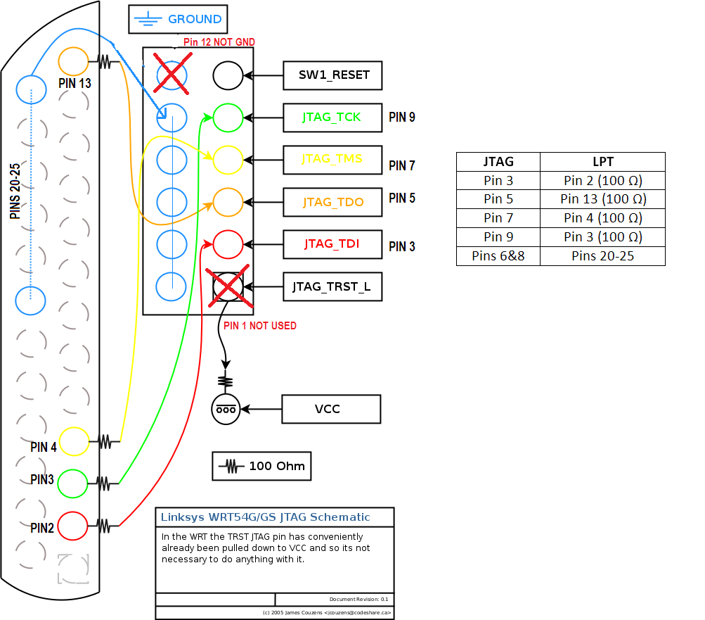
After discovering which connector is the right one, I had to find out the pinout. This was not an easy task, either. Some tutorials used pin 12 for GND, while others forbid it (and used pins 4,6,8,10 instead). I went with the latter, since by looking closely at the PCB pins 4,6,8 and 10 are obviously hard-wired to GND.
Here’s the pinout I guided myself by
and what my connector looked like after soldering it on the router board.

Building the JTAG cable
I used a couple of front panel header cables (hdd,power,reset) I had collected in time from various old cases. I grouped the 6 cables I used to fit in 3 header connectors (2 double, 1 triple).
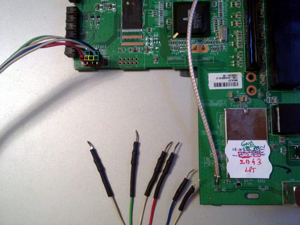
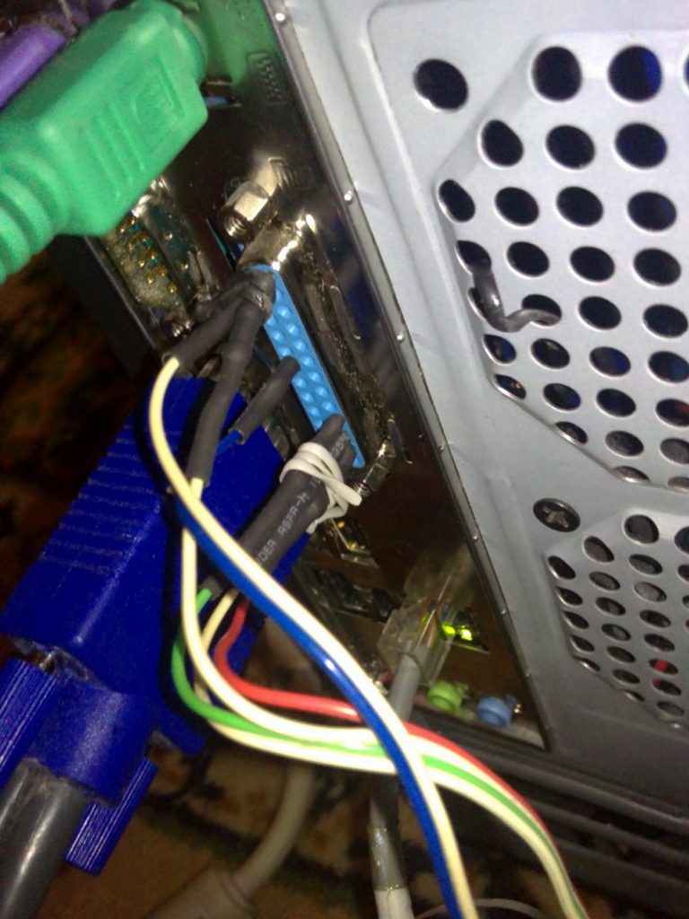
So I recycled a LPT connector from an old printer cable, unsoldered all its wires and soldered my own wires. Inside the thermal tubing are the required 100 ohm resistors.
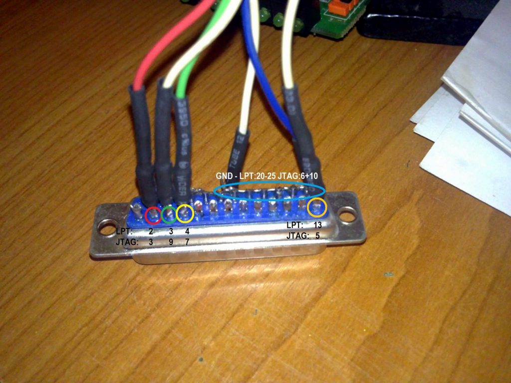
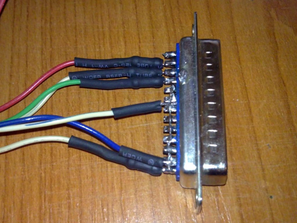
And here’s the entire cable…
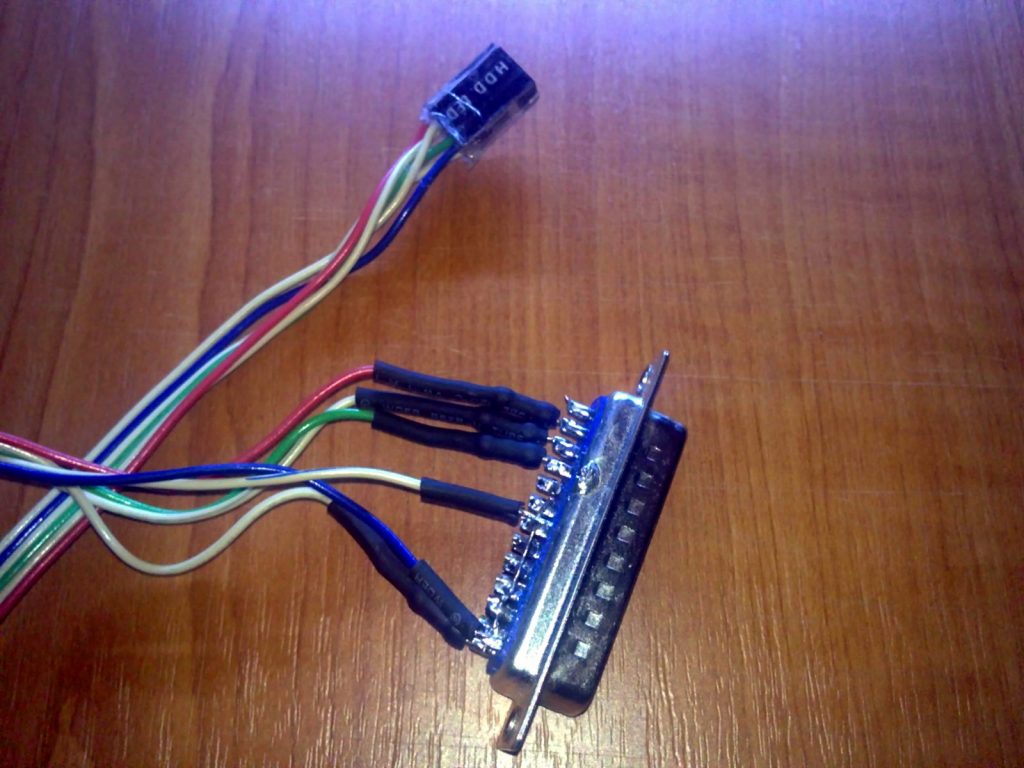
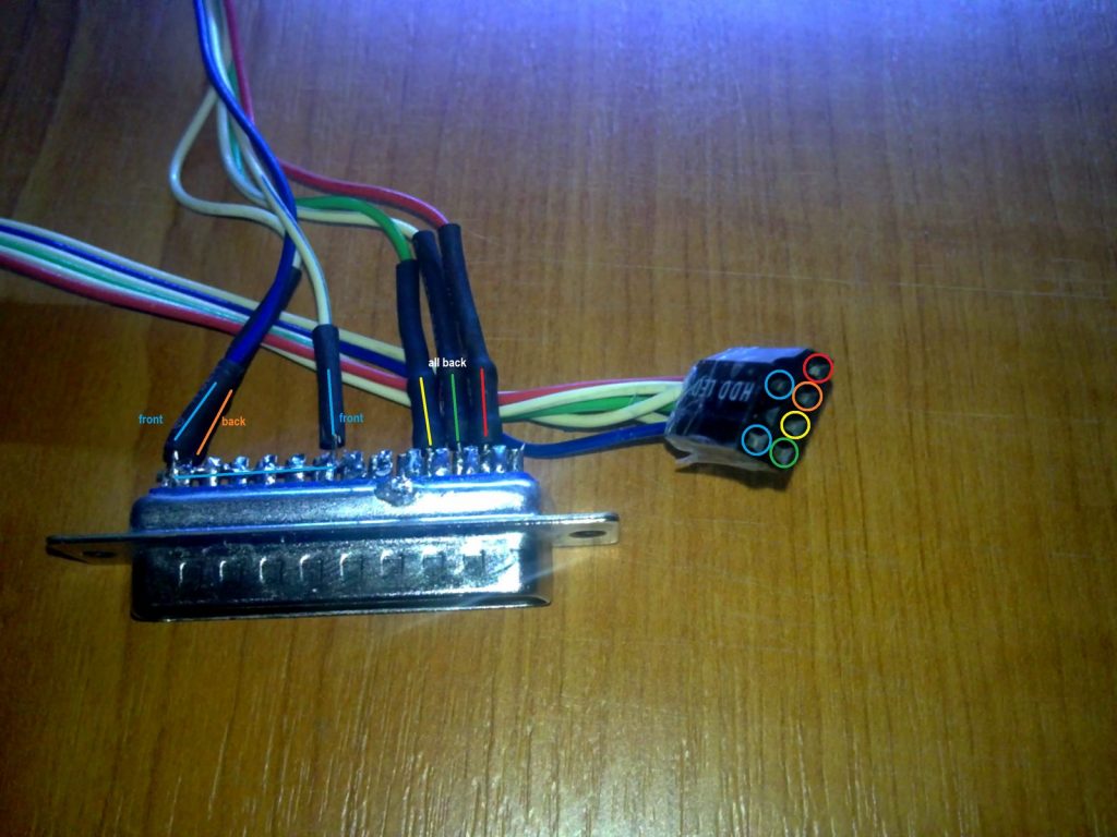
Do note that the wire cables colours do not match the schematic colours, so don’t get them mixed up 🙂
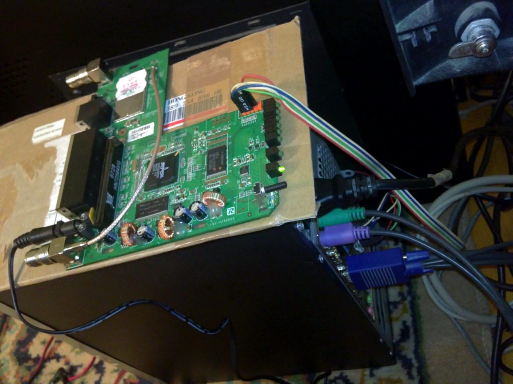
And finally, the whole thing at work…

part 2 ?!!!
Hello, I have done this with exactly this cable, and used tjtag v301. If using Linux, it may be need to rmmod lp, because it locks parport0 device.
Hi, where are the part 2? Please i need it… Thanks
Hello!
Can you tell me what kind of jtag uploder sis oyu used? tjtag? or wrt54G ? i have the same 1.1 but with another flash chip made by EON.
Wait for your replay. Regards.